Case Project
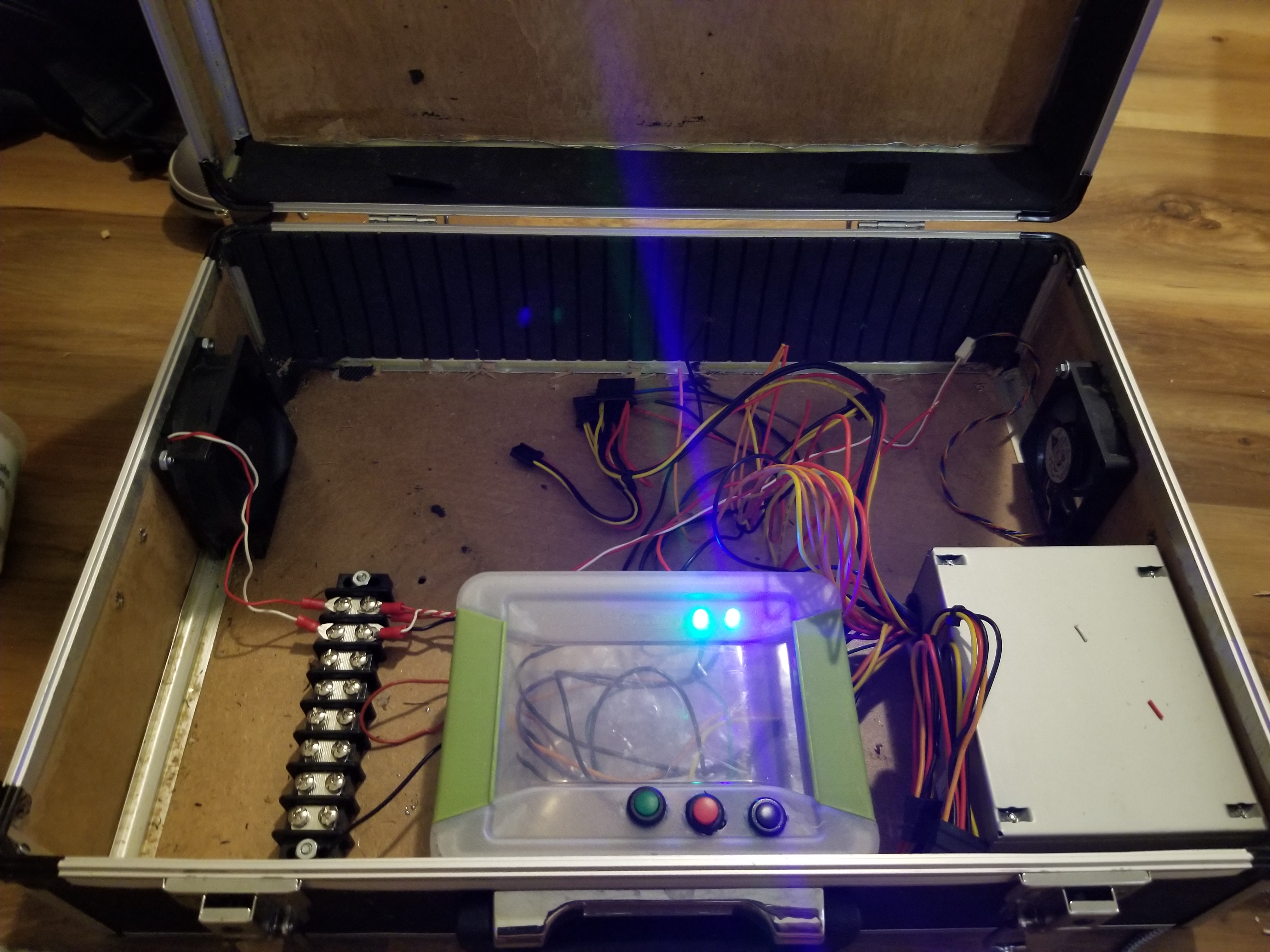
Using a harbor frieght case I installed a computer PSU and other electronics. To create something that was like a cyberdeck but was more open to modification.
I also installed a network switch and fans and have switches to control the power going to the network switch or to the fans or to the rasperry pi.
Power Supply
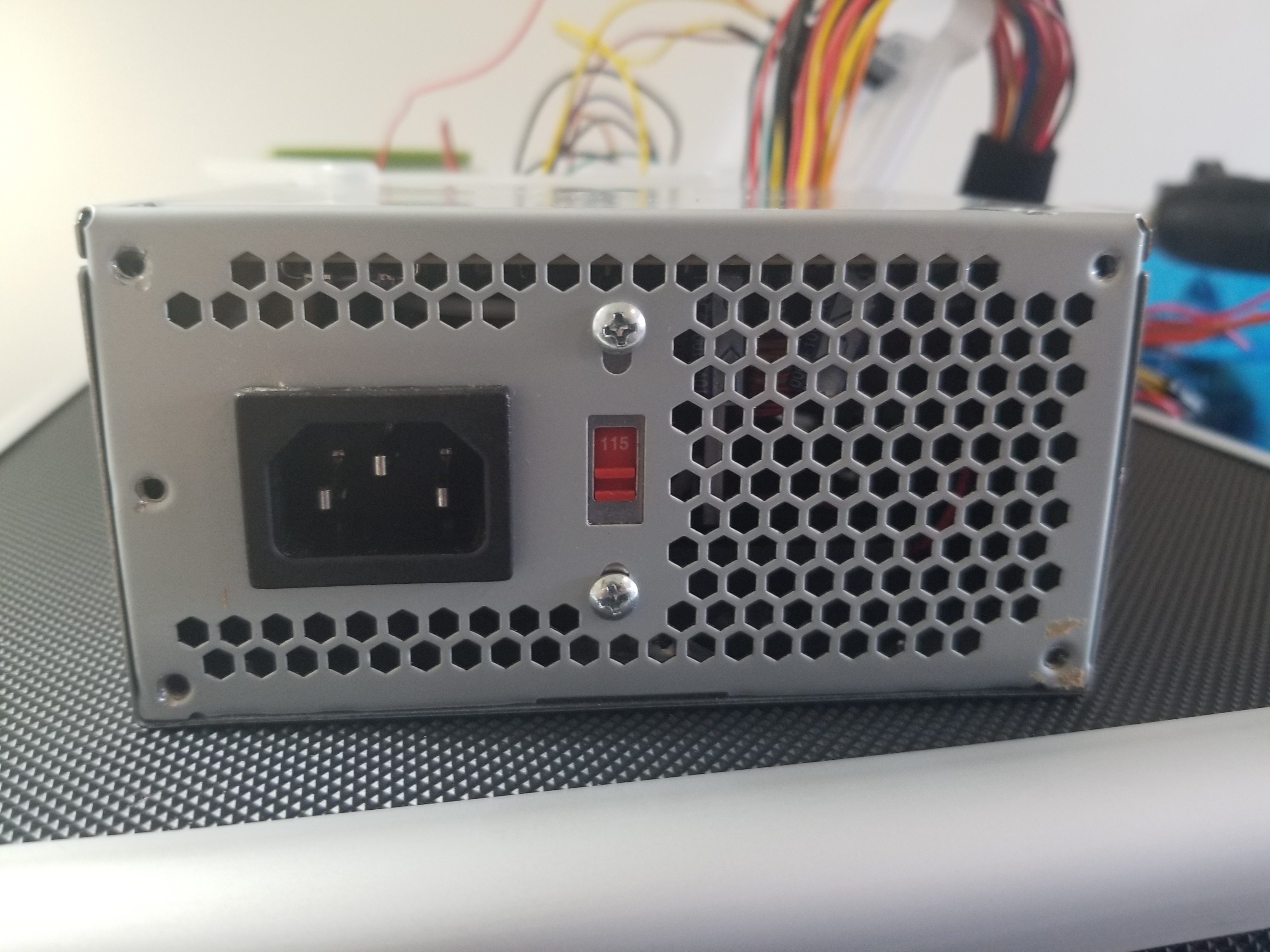
The power input side of the power supply.
Noting all of the locations where there are screw holes.
Tape for marking
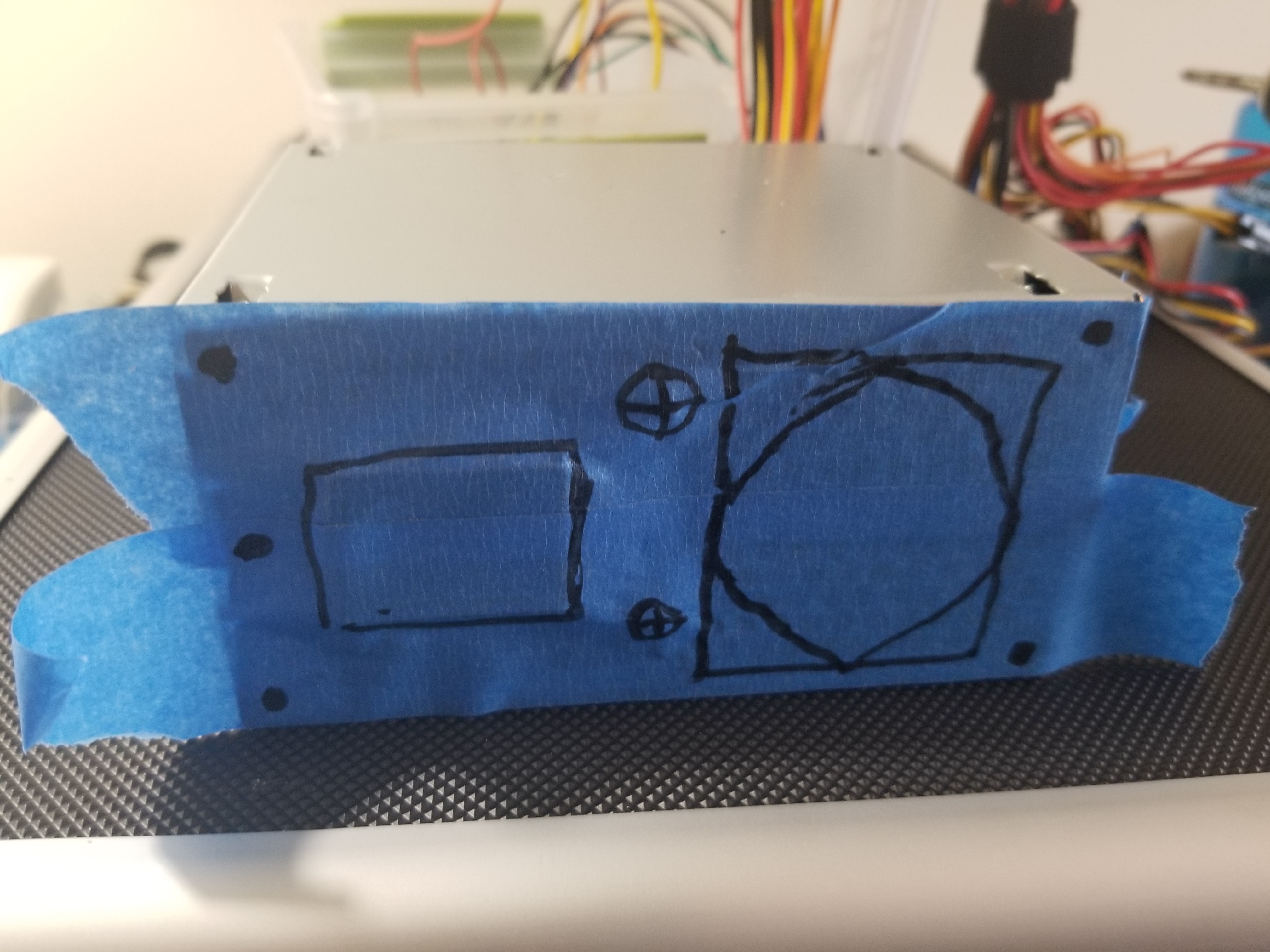
I applied blue painters tape.
Marking with a marker where all the protusions were like the two phillps screws in the middle and the power inlet plug.
Also marking where all the screw holes were.
Tape for marking
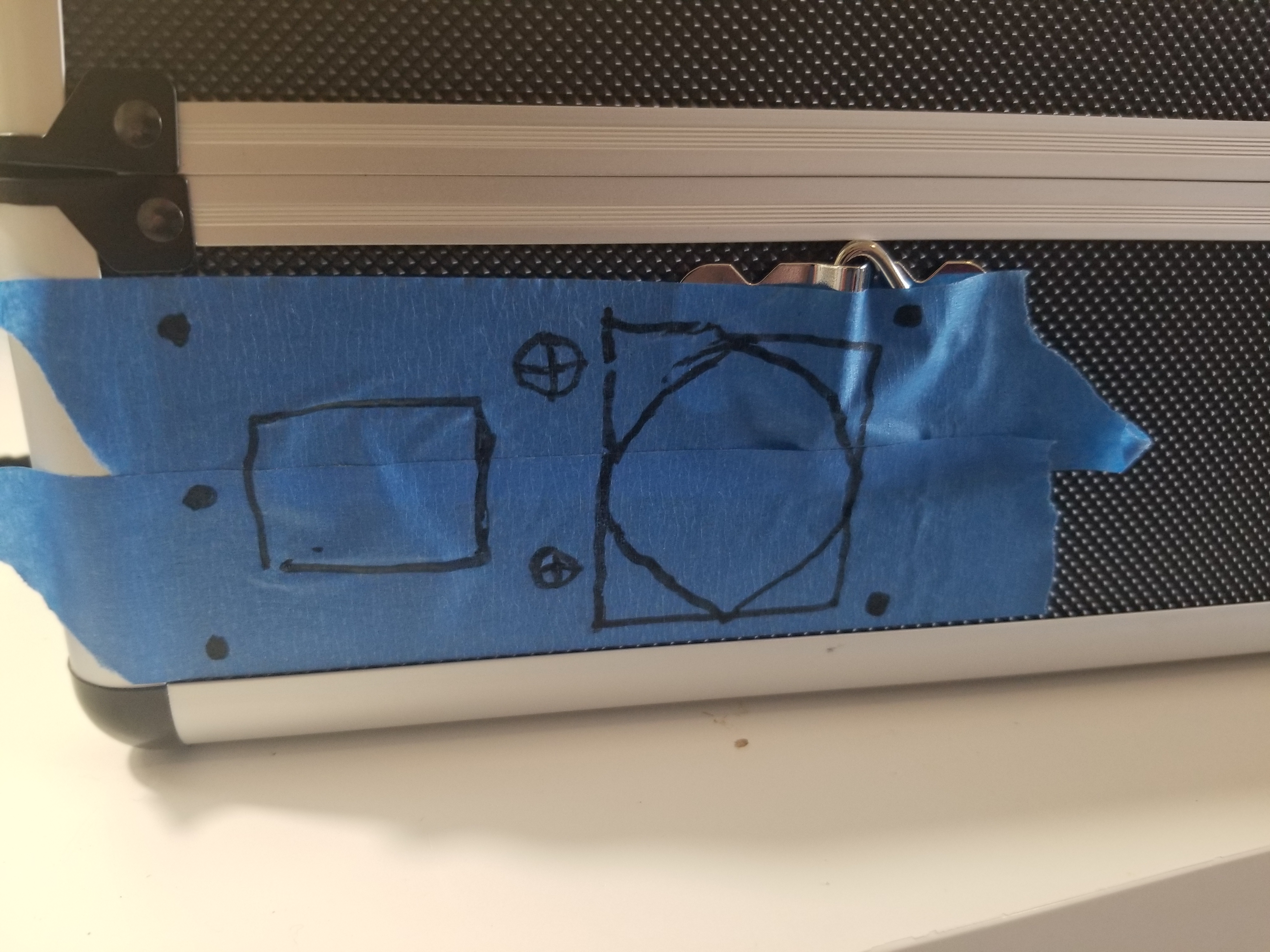
I then removed the blue tape and applied it to the case keeping in mind the size of the power supply so I wouldnt drill the holes where the power supply wouldnt fit.
Power Supply
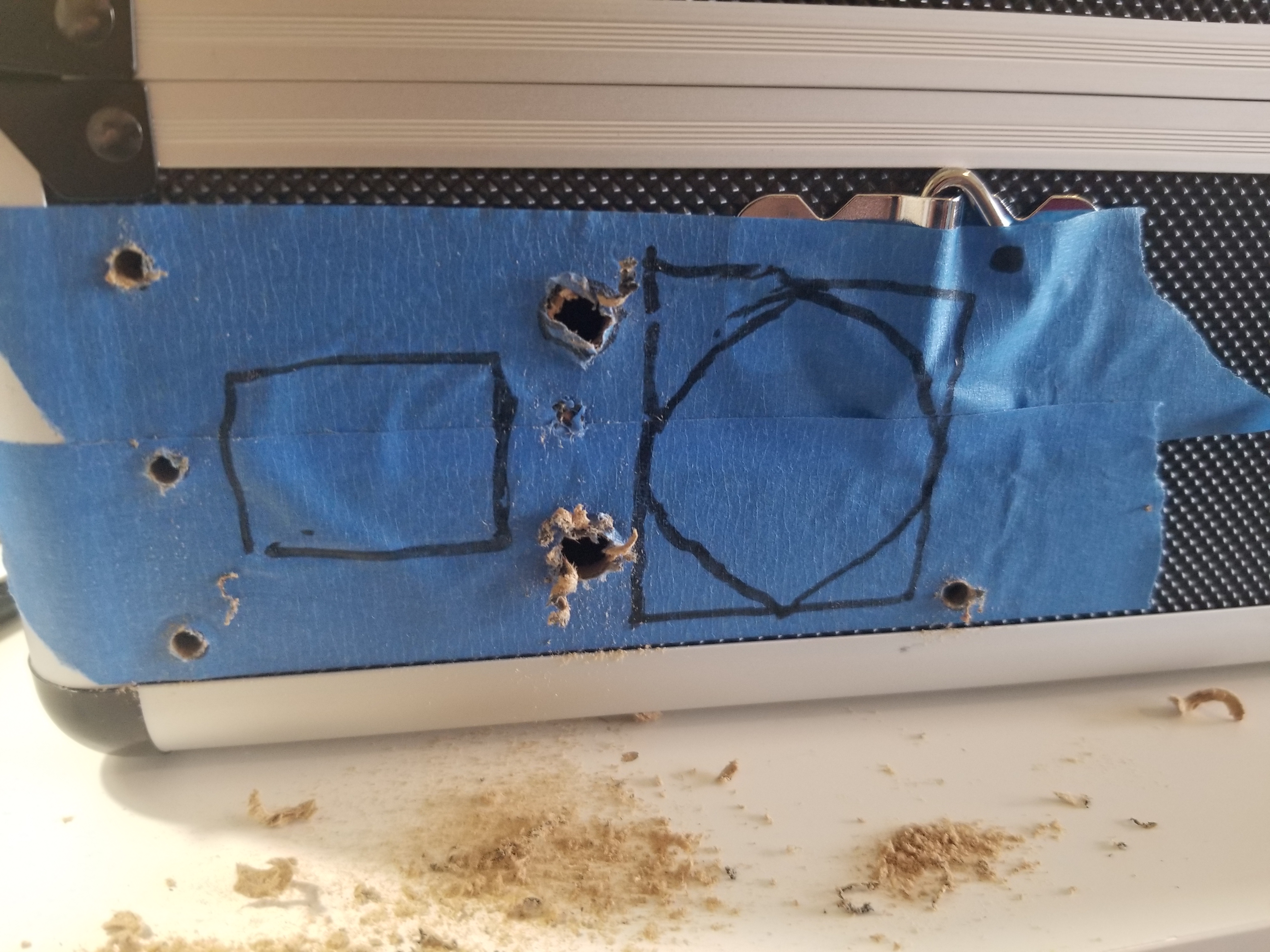
Then I drilled the holes for the power supply, the two middle larger holes was for the phillips screws that I mentioned earlier.
Power switch
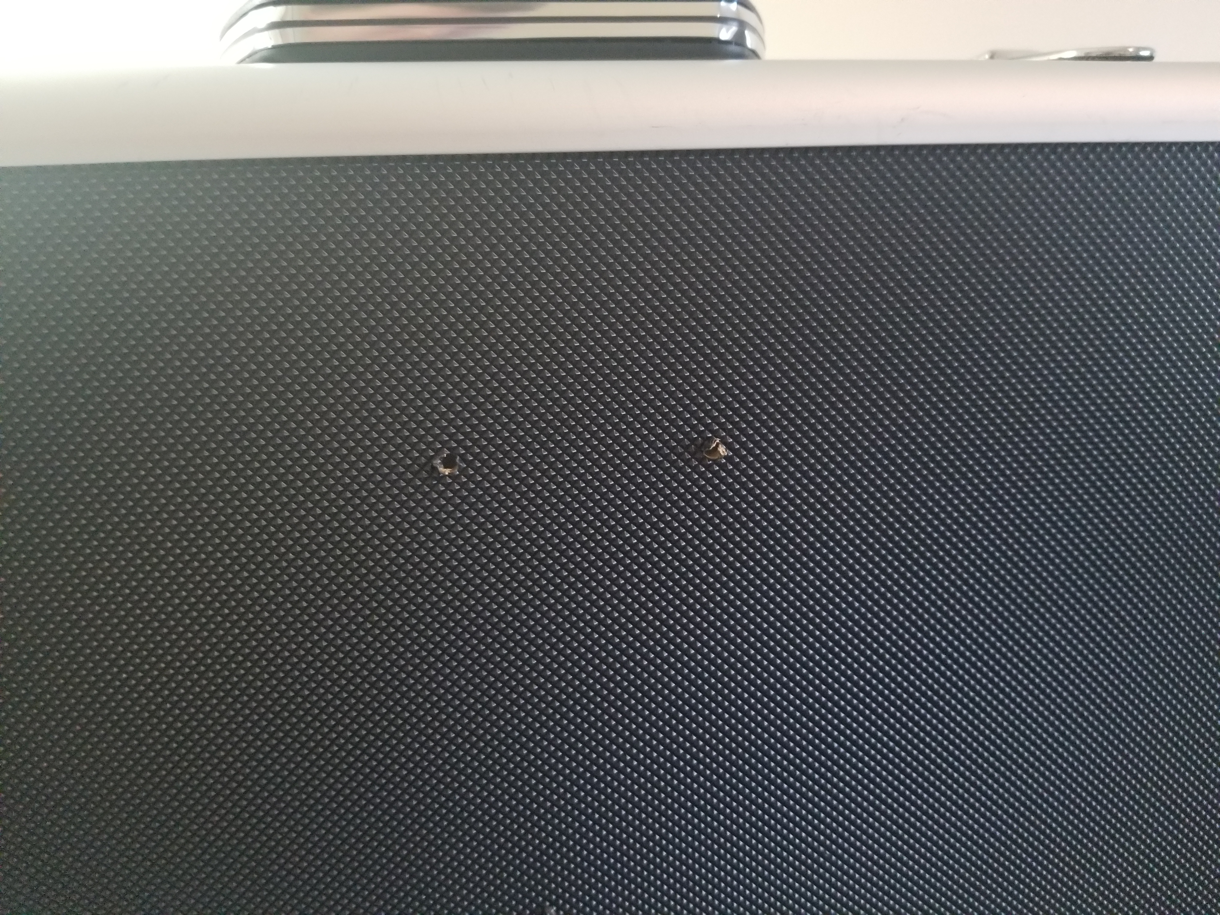
I drilled the starter holes for the tupperware container in the center of the case for holding the switches and indicating LEDs.
Power Switch Box
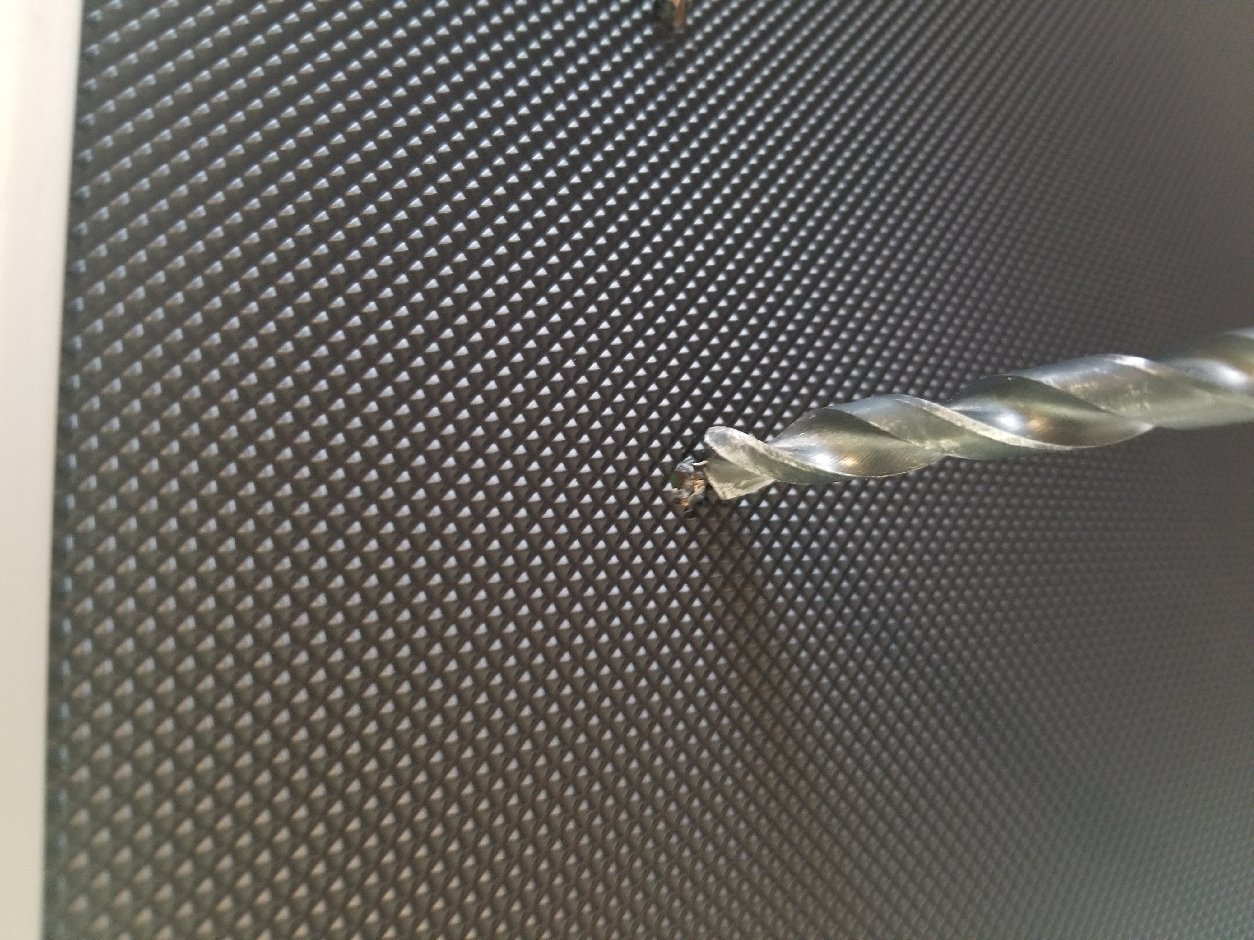
Then I drilled the holes with a larger sized drill bit that was a slight bit bigger than the screws I was using.
Power Switch Box
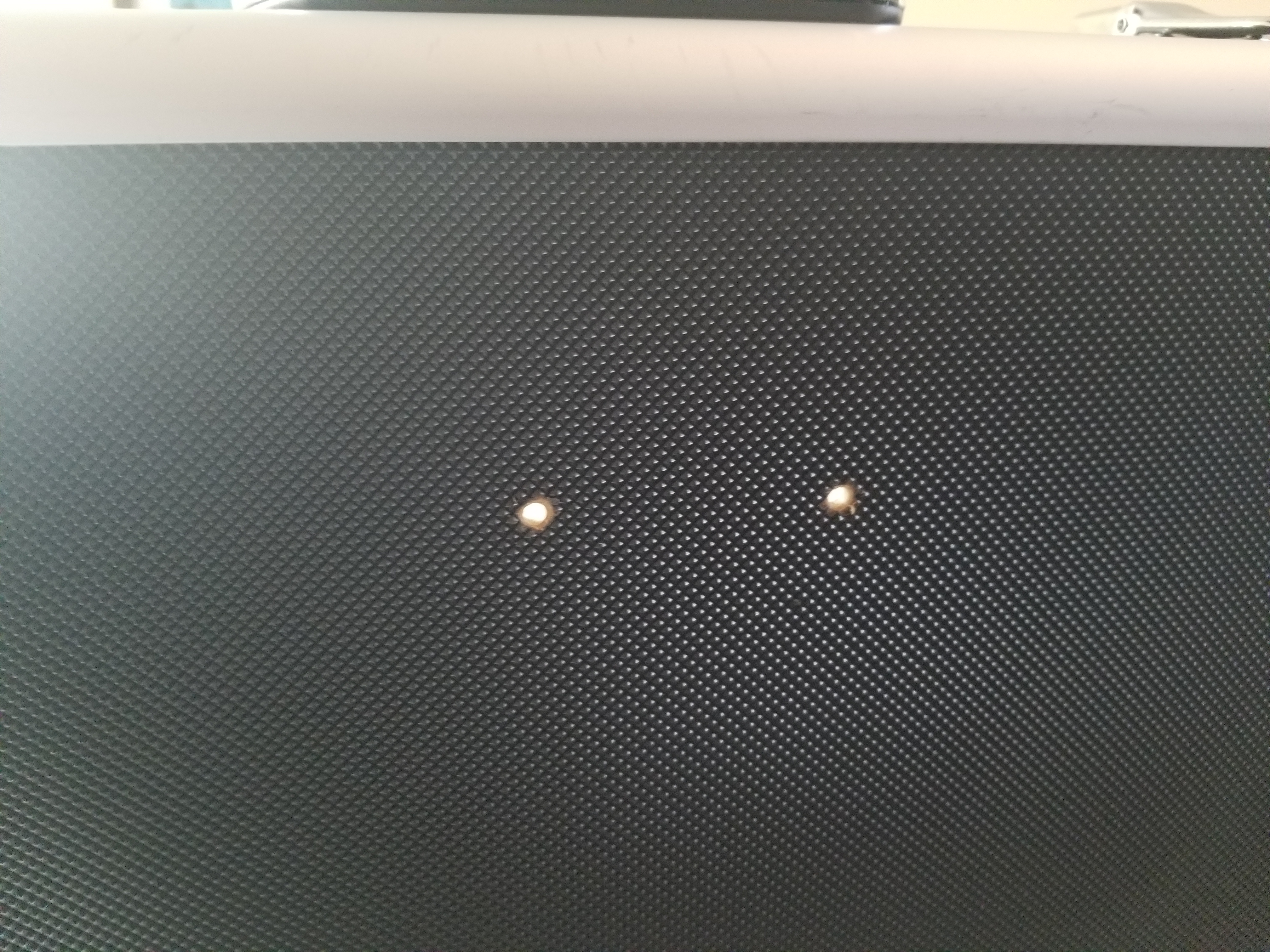
The two larger holes drills.
Power Switch Box
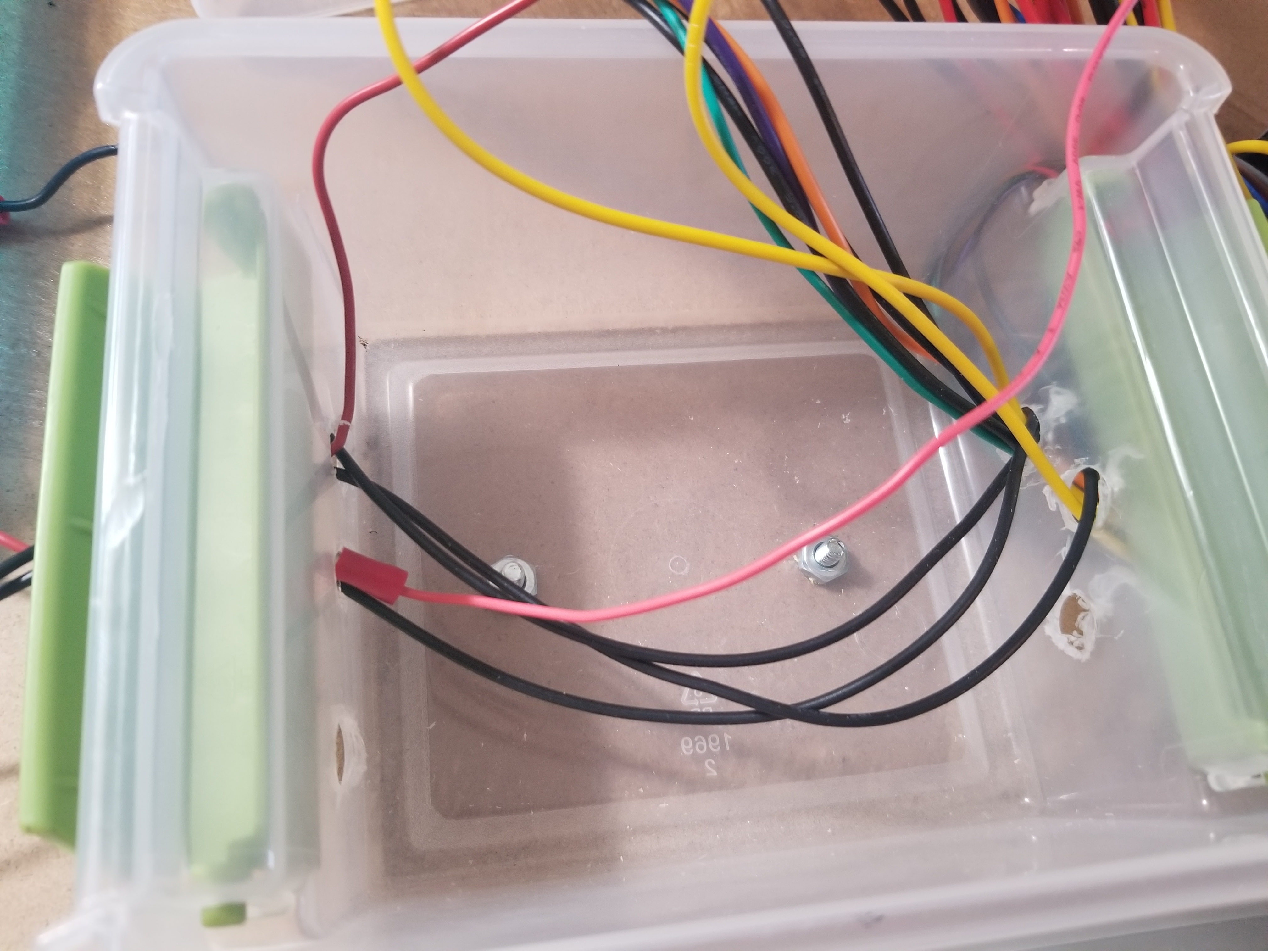
The screws installed with the box and nuts holding the screws.
Indicating LEDs
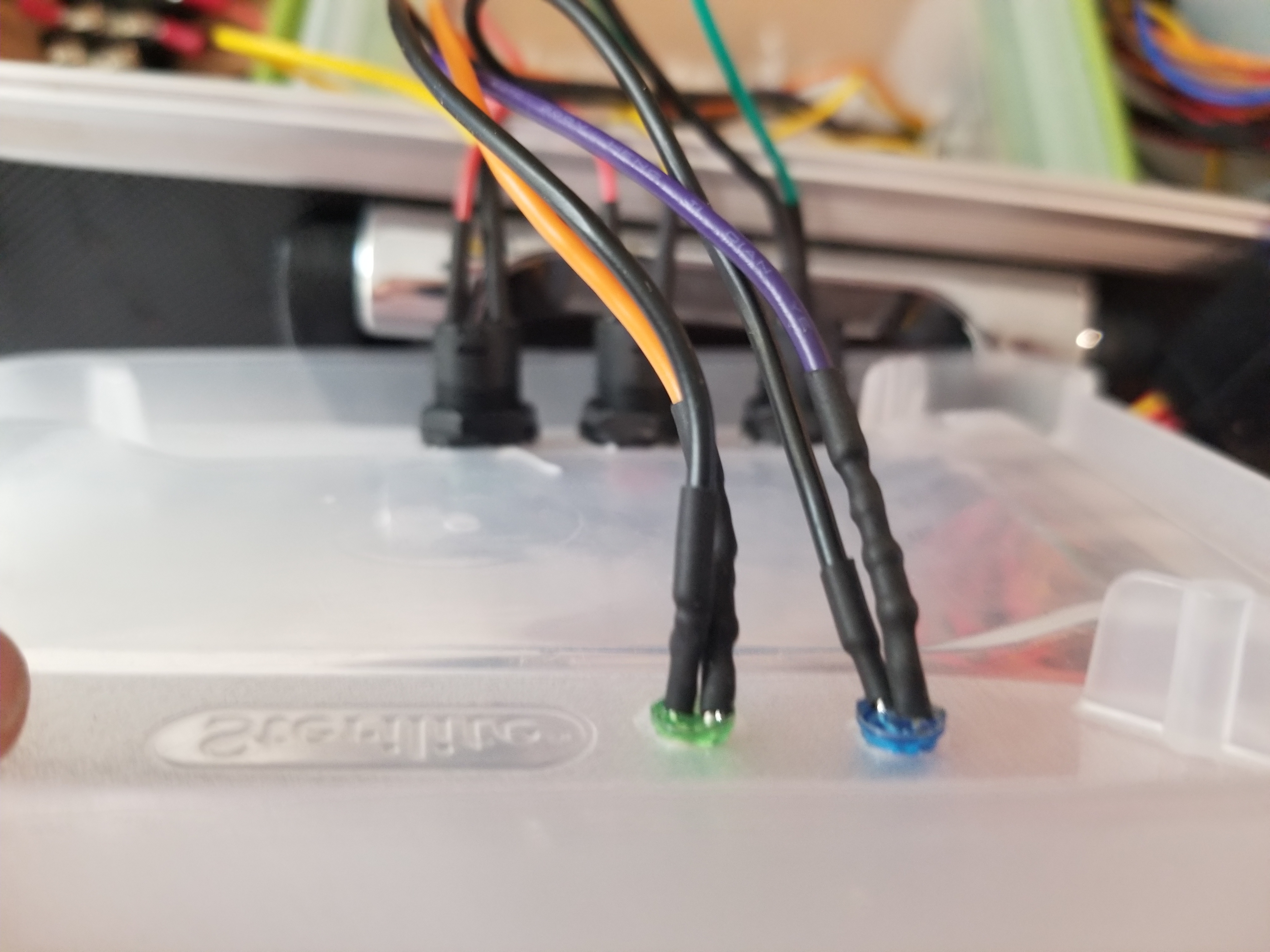
The blue led is a power indicator light connected to the purple wire from the PSU, the purple wire has 5 volts of power once the PSU has power without it being turned on. In between the LED and the purple wire there is a resistor soldered to drop the voltage to safely power the LED.
The green LED also has a resister soldered in to protect the LED. The orange wire supplies 3.3 volts which turns on whenever the power supply is energized.
Power Switch Box
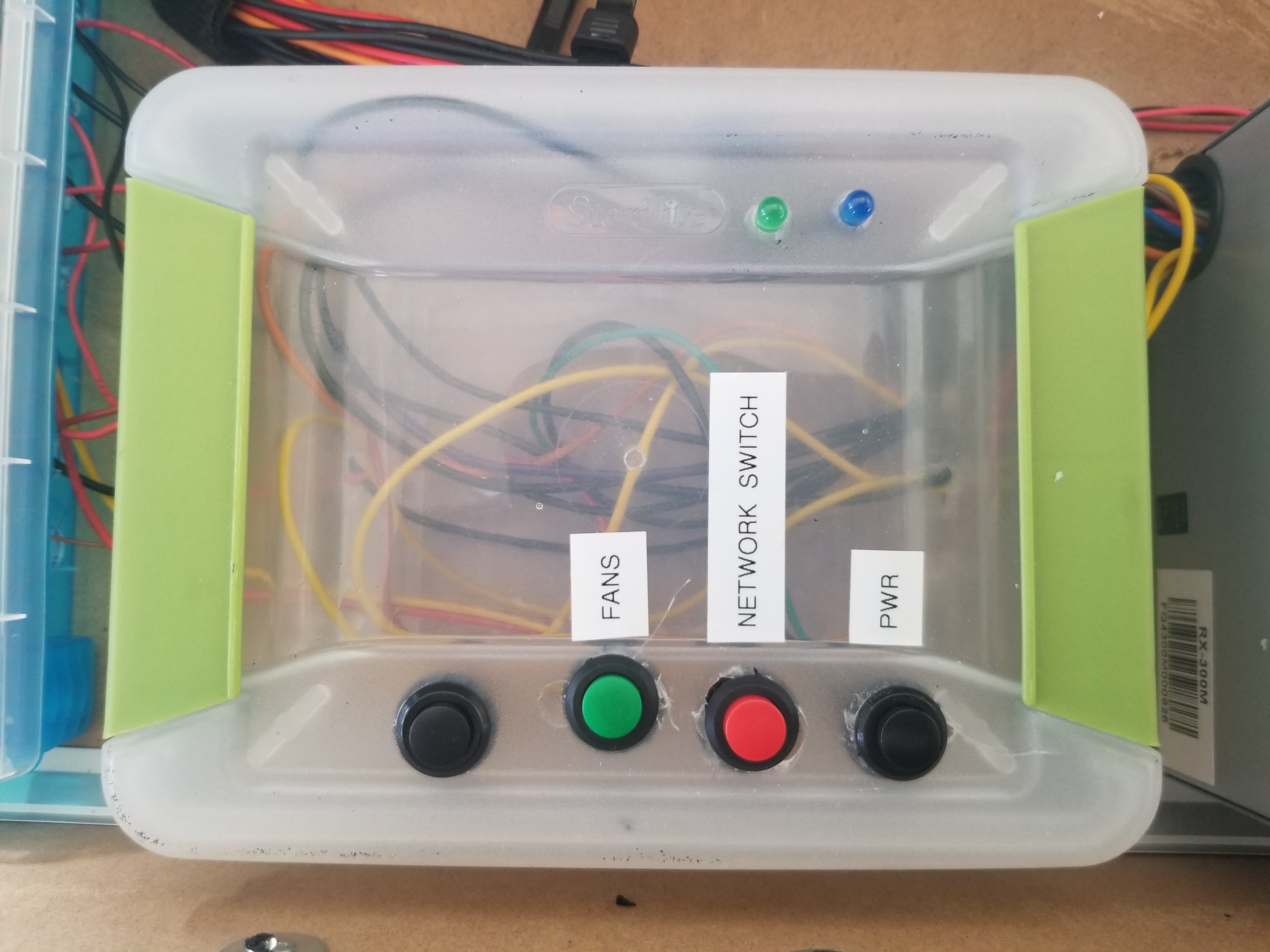
The different buttons get power from the computer power supply.
From the buttons power go to the terminal block.
Computer Fans
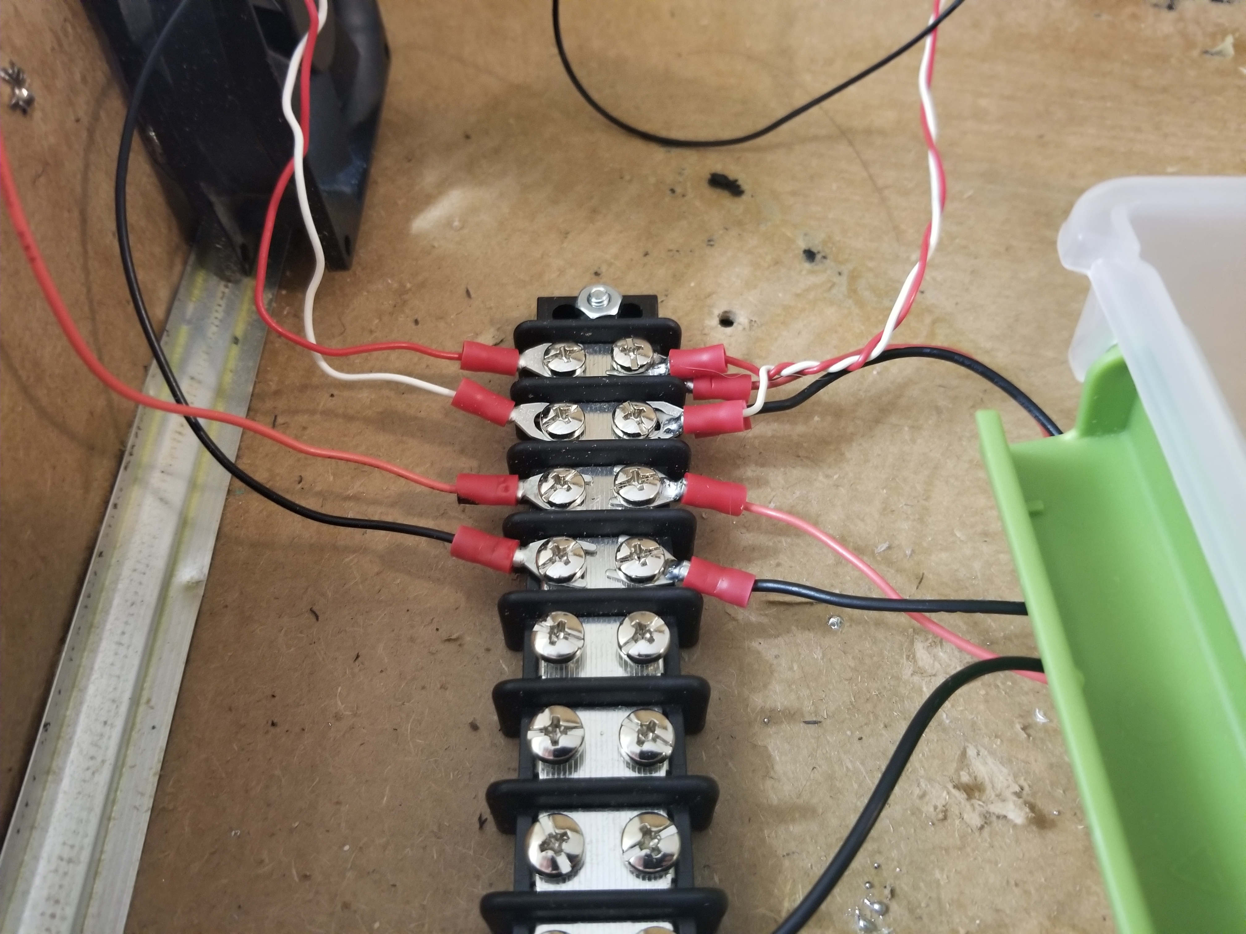
I first mounted the terminal block as shown in the picture. But I didnt like having the open live wire terminals open so I later decided to install a case.
The black wire going to the second row of the terminal block is the ground wire for the 12 volt computer fans. The 12 volt power supplying the fans is on the first row but is covered up by the ground wire in the picture.
The red wire on the third row of terminal board where it is terminated as to allow modification of the case as per the project needs. The black ground wires coming straight from the PSU also terminates on the forth row of the terminal block to alow future modification.
The wiring on the third and forth row is 12 volts for the network switch.
Terminal Block Case
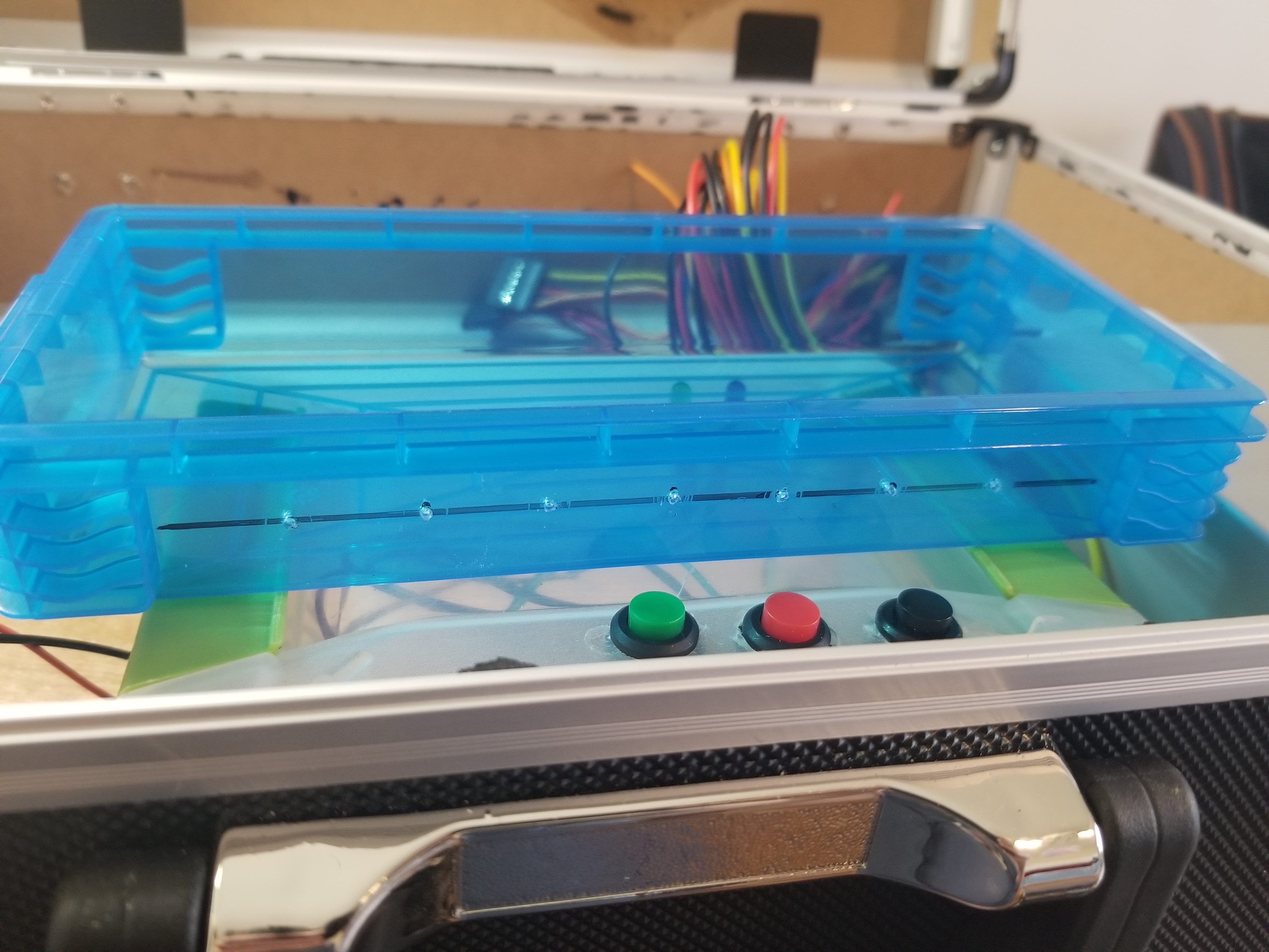
I got this case from Michaels the craft store, I think it was intended as pencil case but I figured it would fit perfectly for my use.
I marked the half inch from the bottom and drilled multiple holes as a pilot hole for me drilling a larger hole later.
Terminal Block Case
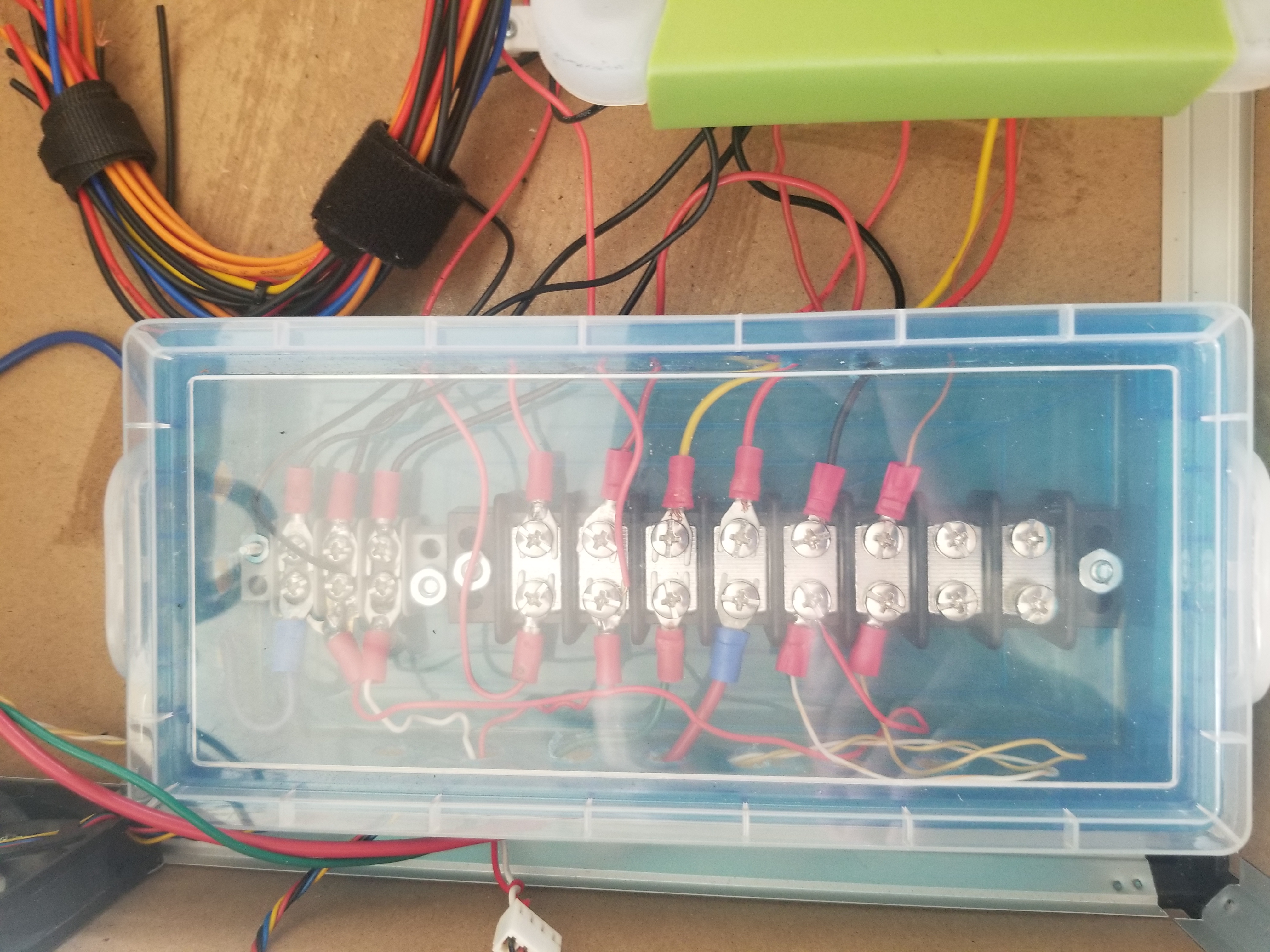
I drilled the holes on the side for the wires and then I mounted the cover along with a smaller terminal block that I use for a ground.
I like this better because then the wires are covered but still visible.
Network switch
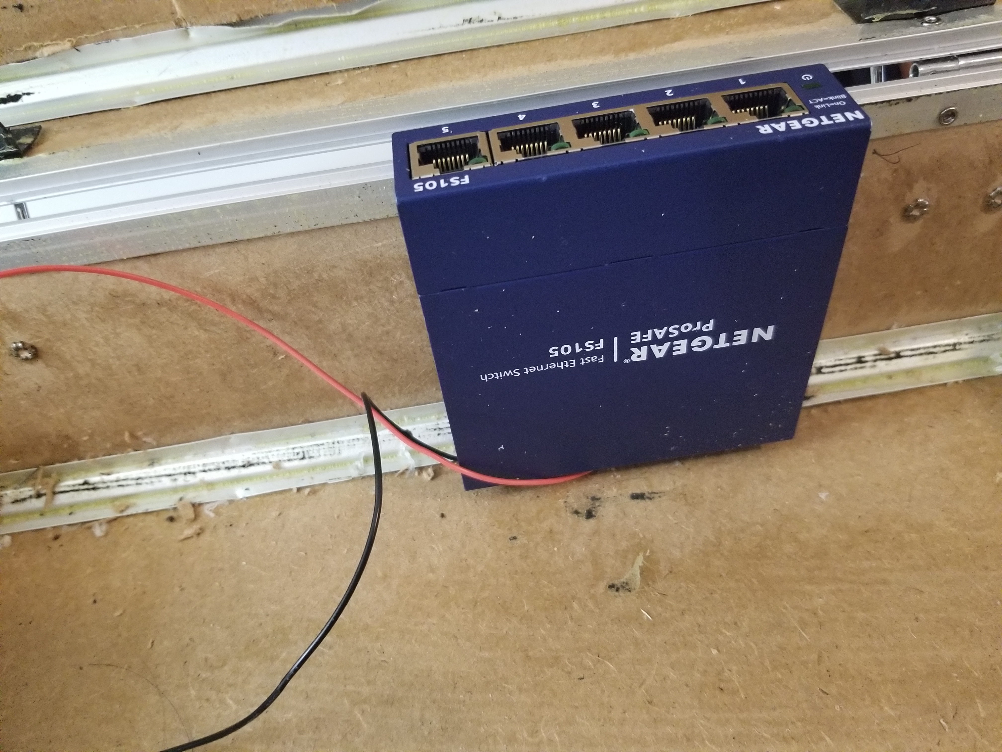
The power port for the network switch is a barrel connector but only requires 12 volts and 0.5 amps which the PSU is certainly enough to supply.
Opening the the switch and analyizing the solder points and barrel connector center pin, utilizing a multimeter on diode mode I was able to determine which pin is the positive and negative.
Indicating LEDs
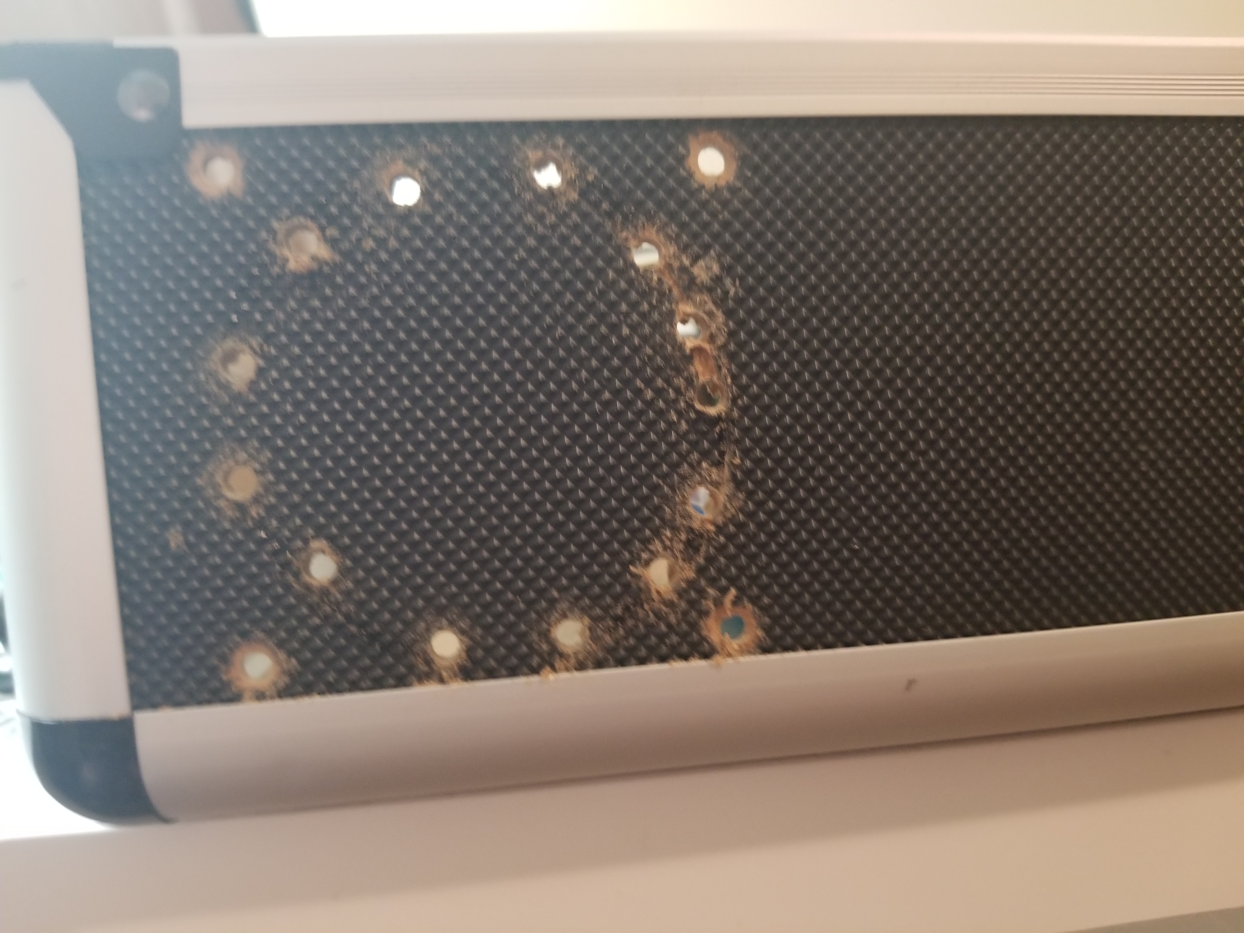
Then I marked and drilled holes for the fans for air circulation.
I cut out the circle made by the holes for the fan to blow through.
Adding Ventilation Fans
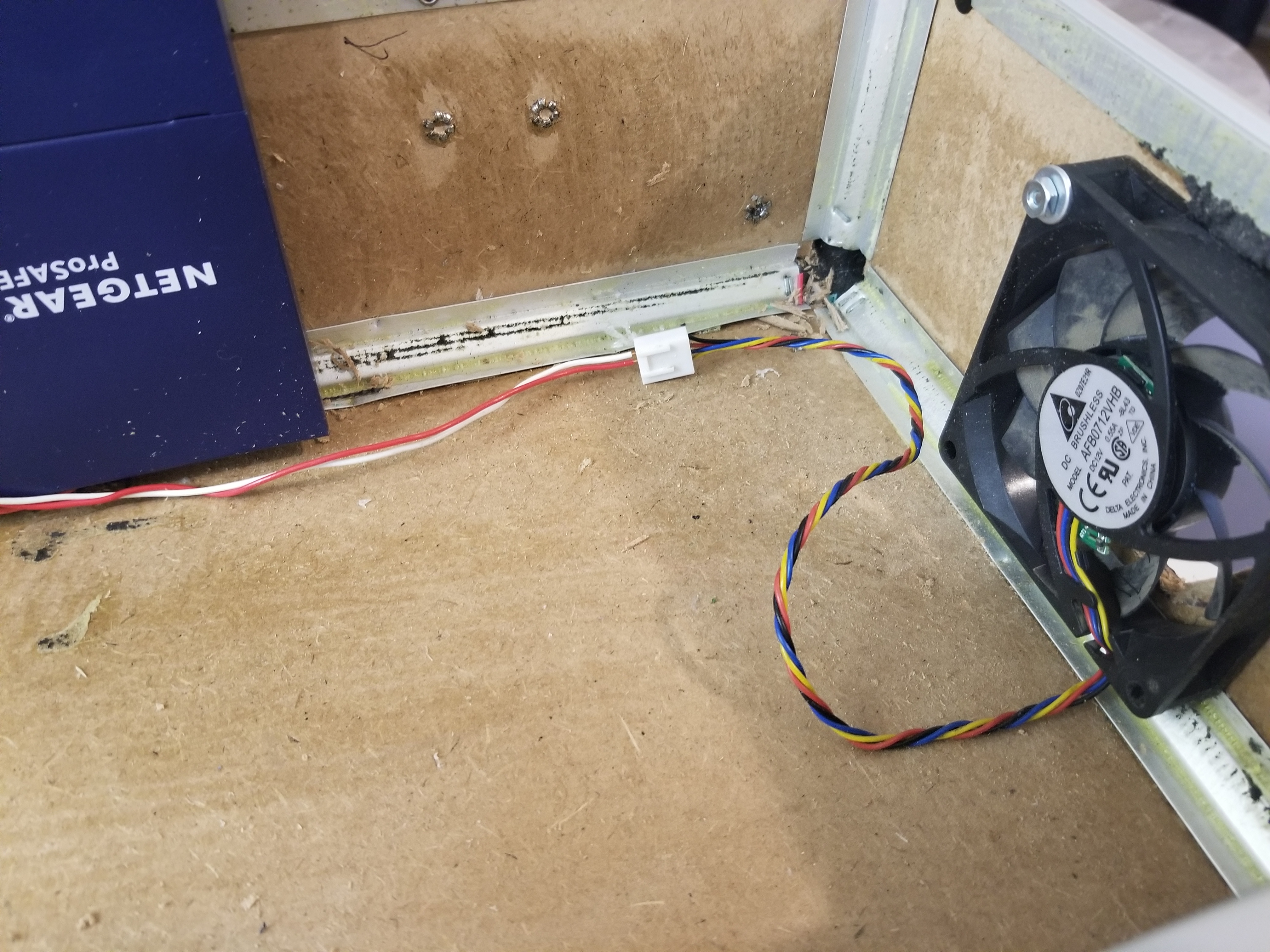
Then I installed the fan with normal screws and washers and nuts to hold the fan to the side.
Cable Management
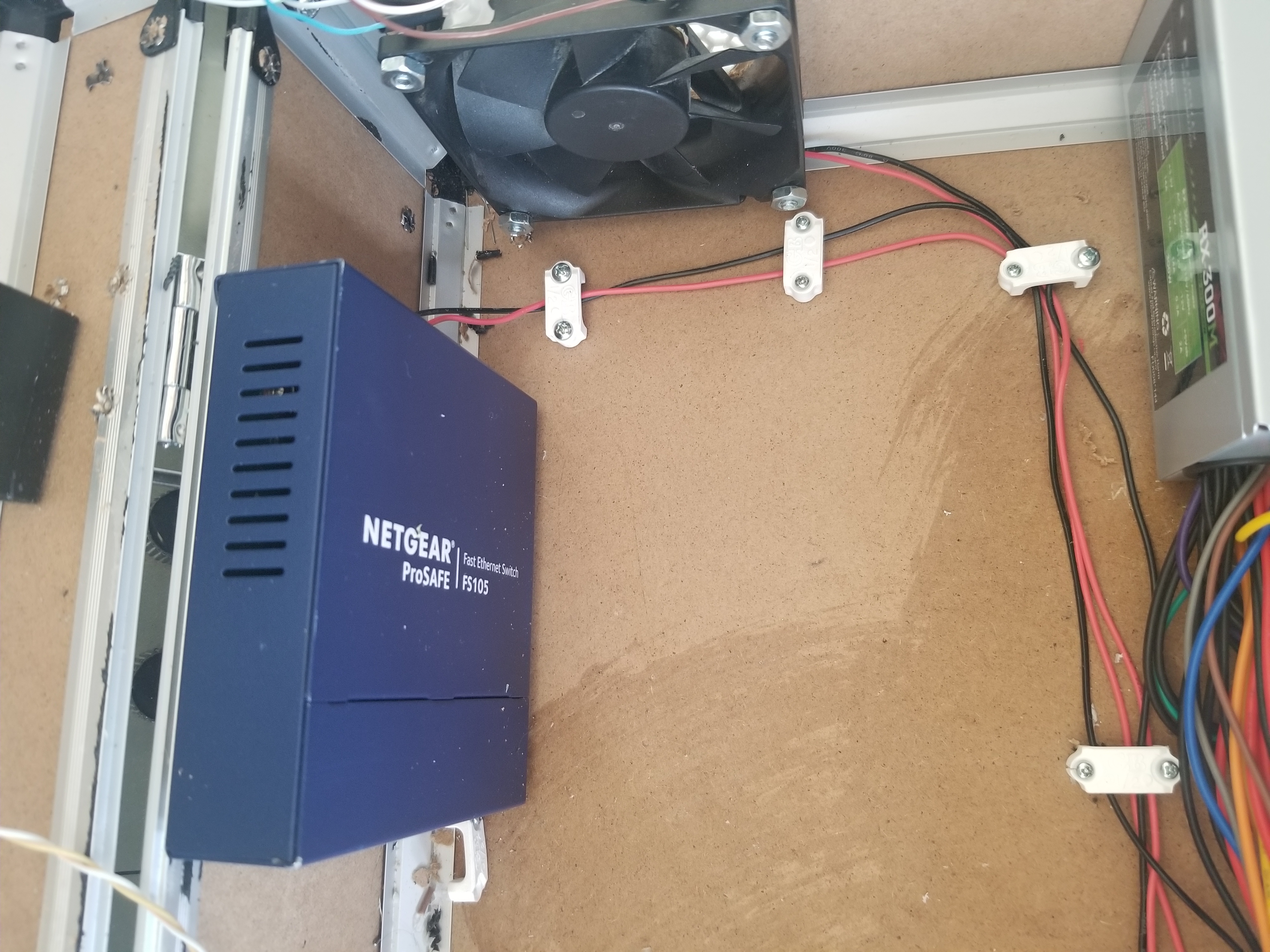
Using cable run brackets screwed to the case for a place for the wires to run.
More Cable Management
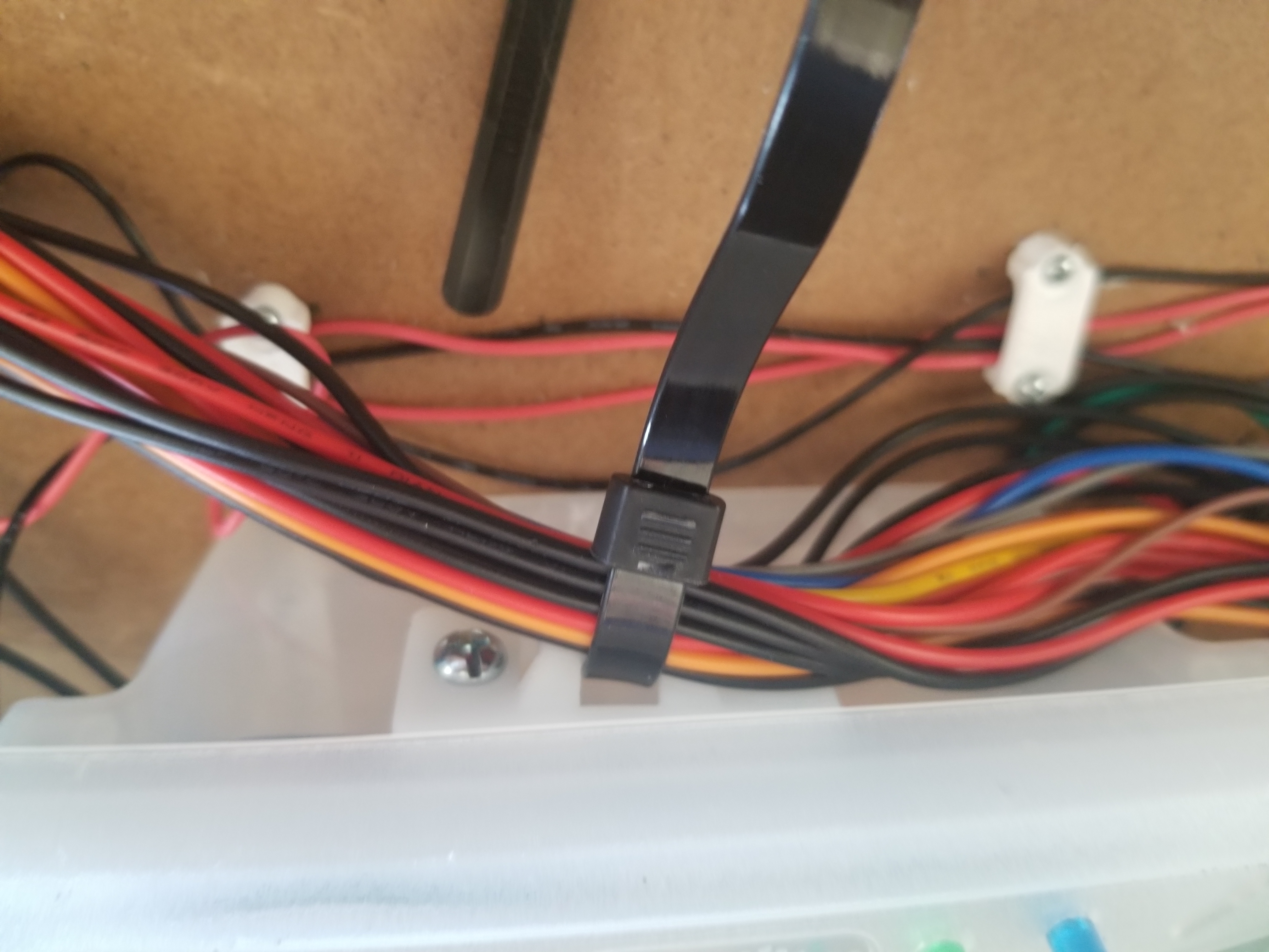
Then I installed a ziptie mount bracket and used a reusable zip tie to hold the larger strands of extra wires from the power supply.
Installing Raspberry Pi
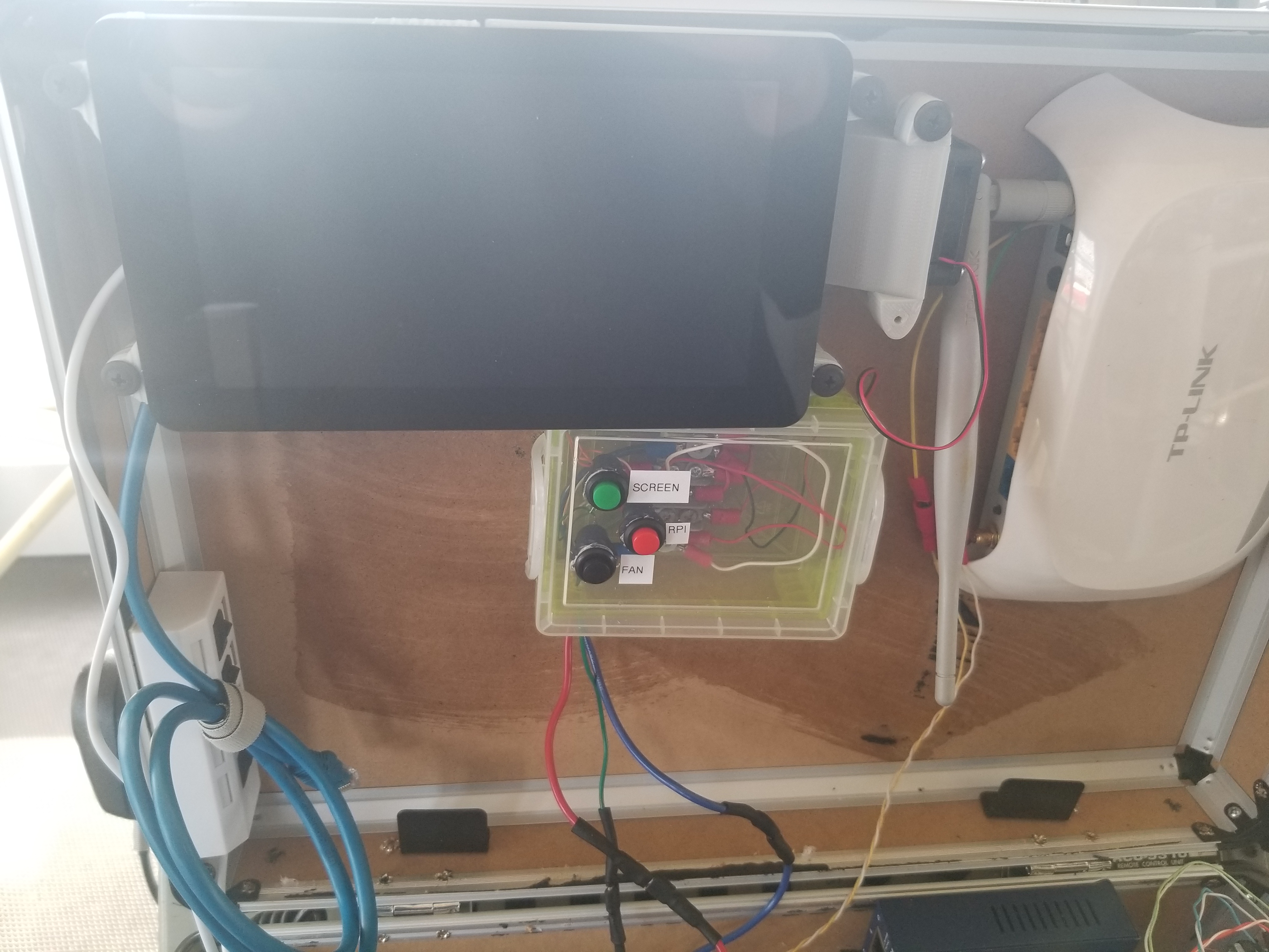
Using a 3D printed bracket I mounted a raspberry pi to the case.
Pre-installed an CAT-5 Cable and a USB hub for easier access to the raspberry pi internet and USB port.
Installing Raspberry Pi cooling fan
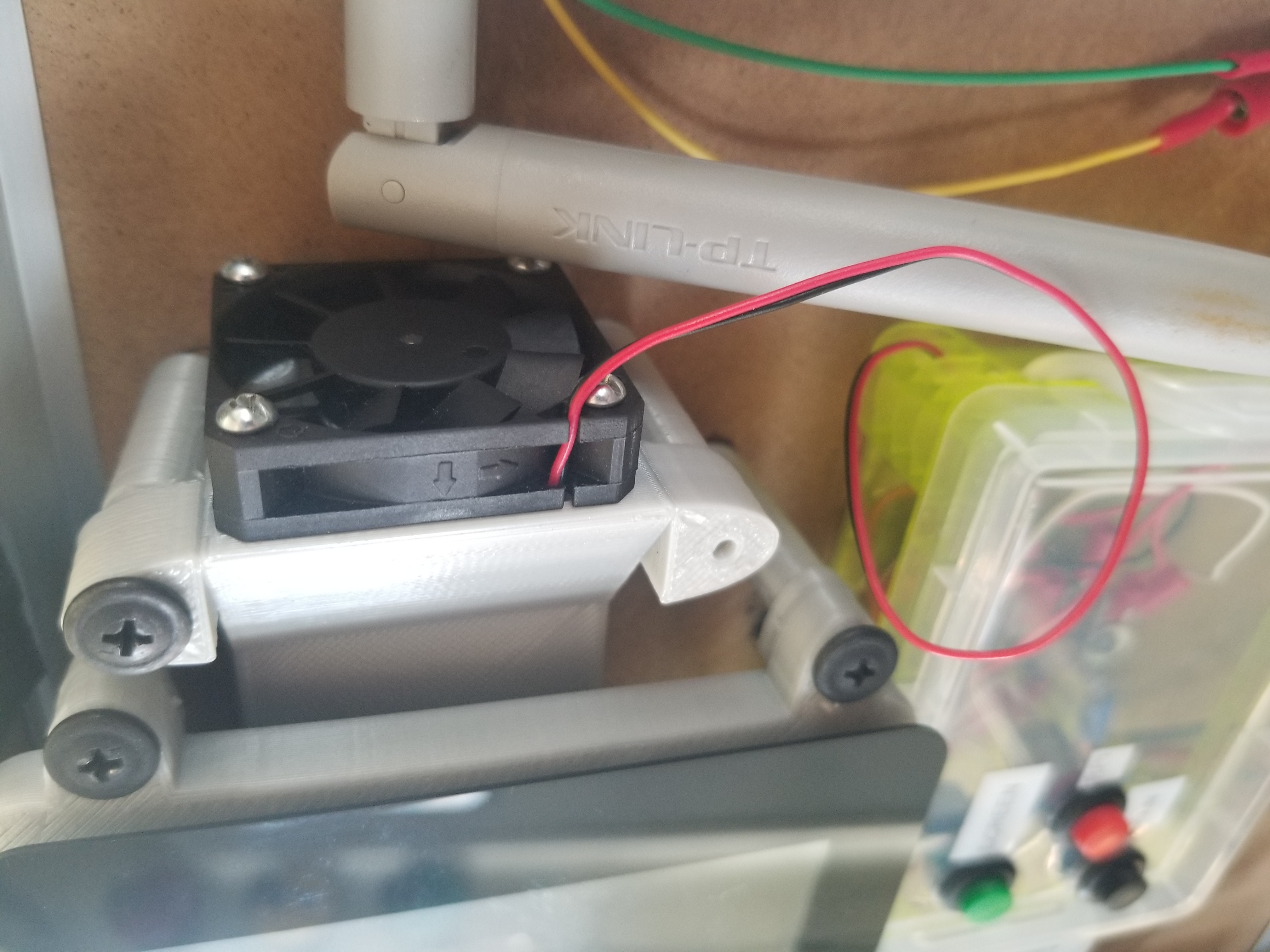
I added a small 12V fan I had using a 3D printed bracket I made to cool the raspberry pi incase it gets hot.
Raspberry Pi Control Box
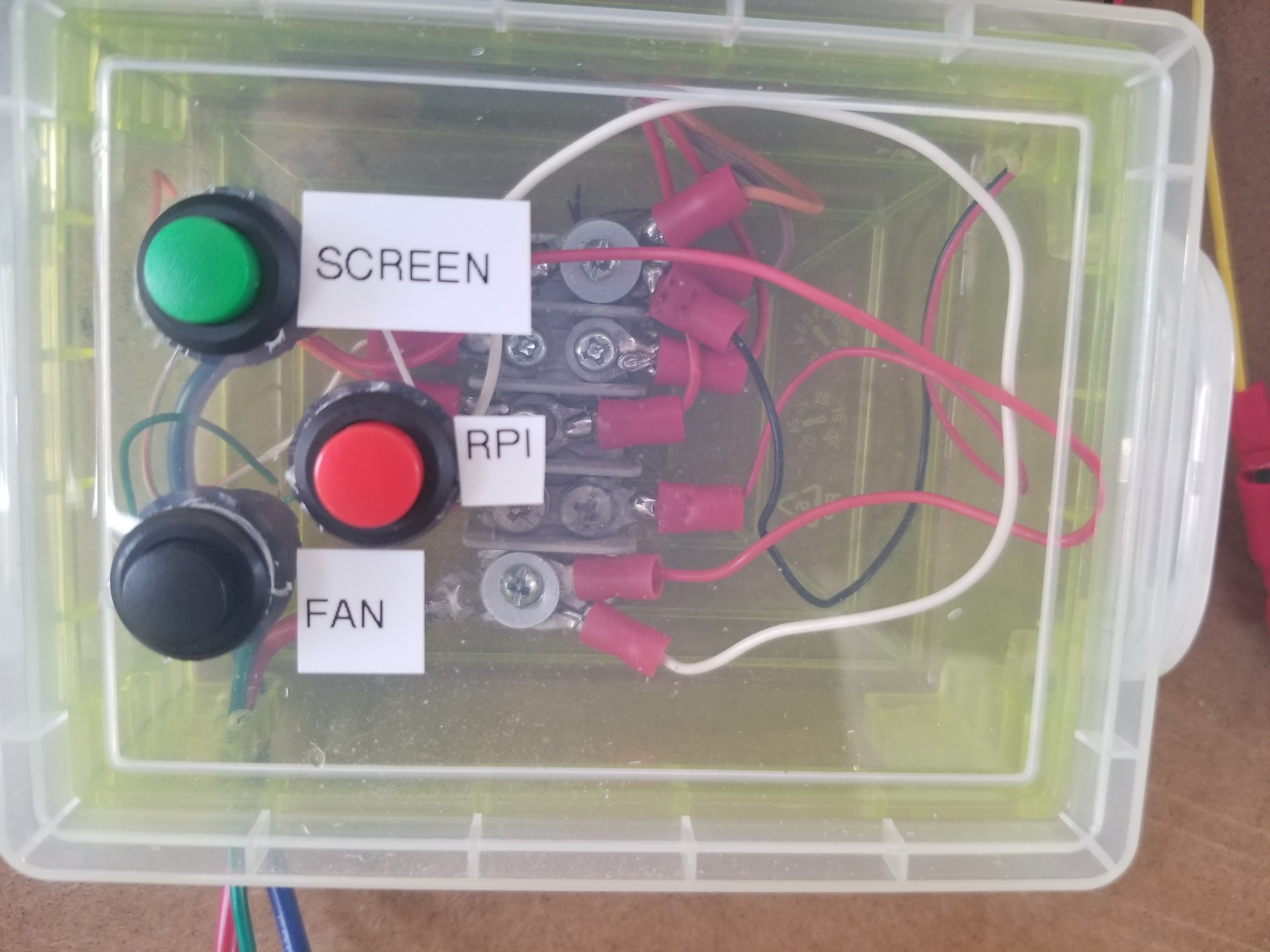
Using stranded wires and connectors I installed buttons to power the raspberry pi and the screen which is 5V but the fan is 12V.
With power of two different voltages I had two wires running up but then one ground wire returning to the main terminal board.
Wifi Router
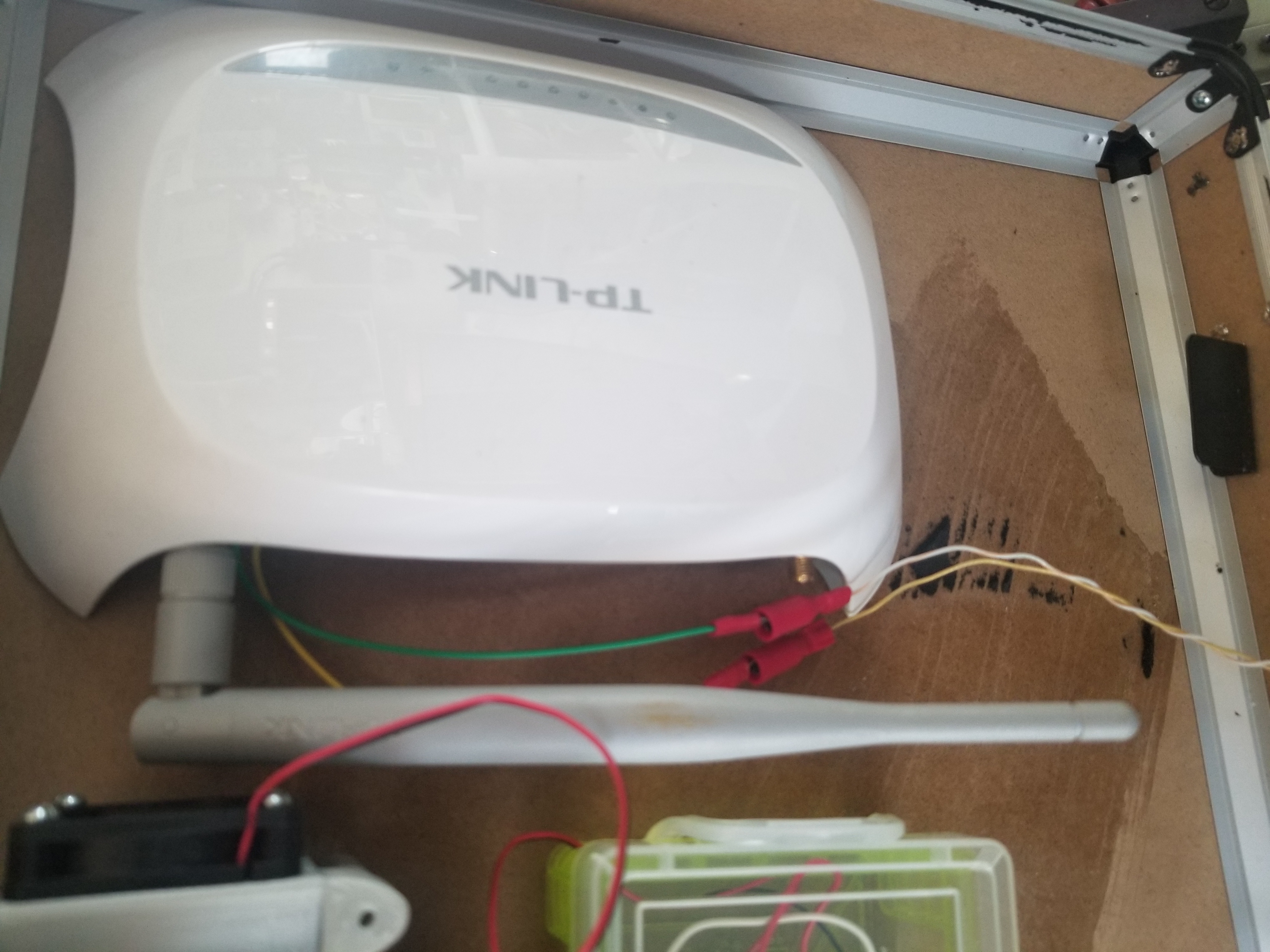
Then I installed WIFI router and connectors providing power to it from the main control box with the 12v connector.
